CALMINI RockCrawler
Calmini RockCrawler Gear Set for the Sidekick / Vitara
Editor: Eric Bewley
ALBANY, OR -With the increasing popularity of the Sidekick as a viable off-highway vehicle, it was only a matter of time before the aftermarket equipment manufacturers started making quality ‘hard parts’ for serious enthusiasts. CALMINI manufacturing has done it again with their one piece RockCrawler gears sets. Reported to be manufactured to exceed factory tolerances from the highest quality material. Stronger, better fitting, and longer wear life are the advantages of their exclusive all new gear. Their complete kit includes new input gear, low output gear, new counter gear, counter shaft bearings, seals, oil and detailed installation booklet. Amazingly, this kit produces a 134 % (4.239:1) low range reduction from stock and fits 91-98 Sidekick/Tracker & 99-01 Vitara/GrandVitara.
We have had this quality product in our two ZUKIWORLD Sidekicks for quite some time now and can happily report that this is indeed a great modification for the Sidekick that transforms it from a dressed-up grocery getter to a world class off-highway vehicle that can hang with almost any crowd. Additionally, the build quality from CALMINI is superb and puts one’s mind at ease that with proper maintenance, this gear set will probably outlast the vehicle its placed in.
One overall comment on the installation of these gears was that we have done several Samurai gear sets over the years and were a little reserved when it came to learning a ‘new trick’ but shortly after starting this project, all the way to the finish, we felt that it was quite a bit easier to perform this gear swap than it was to do the Samurai. Overall time for use was approximately 6 hours with running to the machine shop to use the press.
 1. Remove 5 bolts and remove gear selector lever case.
 2. Next remove 4wd switch and take out steel ball.
 3. Remove bolts fastening center case and middle case halves together.
 4. Next, use large slotted screwdriver or similar object to lightly pry case halves apart. Check shift rods for any binding that may occur during this step. Pry the case apart by hand after checking shift rods.
 5. Remove counter gear from case by sliding gear off of shaft. Remove needle bearings, spacer, shaft, and thrust washer from case.
 6. On the top of transfer case, loosen gear shift locating spring plug and take out spring and locating ball. It is helpful to use a small pointed object such as a center punch or ball point pen to remove these items. Spray carb cleaner or similar liquid into the hole to loosen these items.
 7. Place your thumb or finger over the opening before rotating the shift fork rod as shown. Remove the spring and check ball from the opening. Use caution as the spring and ball will come out rapidly when the fork is rotated.
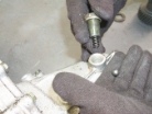 8. Remove the bolt that loads the select lever. Dump out the check ball from the small opening.
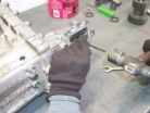 9. Using a punch, drive spring pin out of reduction shift yoke.
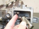 10. After pin is removed, remove reduction shift yoke.
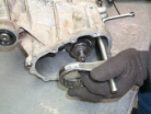 11. After removal of yoke, slide shift rail, fork, and clutch sleeve out of case assembly.
 12.Remove cir clip and then remove clutch hub from main output shaft.
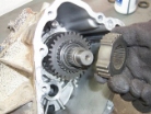 13.Remove the reduction clutch hub from the main shaft.
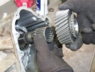 14.Remove low output gear and bearing from main shaft.
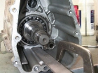 15. Removal of case material is required to install the new larger diameter low output gear. This area of the case is tapered and gets thicker in diameter towards the interior of the case. The total amount of material removed will be .080 -.120 (less than 1/8) This is completed simply by using the sharp edge of a metal file. By sliding the gear and inner bearing assembled onto the shaft into the case, you can gauge the proper amount to be removed. Remember, the required area of material removal is only the width of the gear face. Be sure to measure from the inside of the case wall outward. Be sure that the installed gear spins freely after removal of material. Remember the old adage: Measure twice and cut once. Remove ALL metal shavings from inside of case before reassembly. This operation should take 15-20 minutes total.
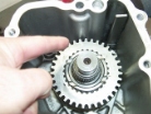 16. After case wall has been indexed, reassemble low output gear and bearing and check case wall clearance.
Assembly
17.Re-install the reduction clutch hub onto the main shaft.
 18. Re-install the reduction clutch hub retainer clip.
 19. Re-install shift rail and fork into case. Do not forget to install drive clutch sleeve over clutch hub.
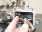 20. Re-install reduction yoke on the end of shift rail
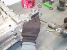 21. Using a punch, drive spring pin back into reduction shift yoke.
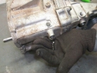 22.Re-install the spring and check ball in the opening in the case and re-install bolt.
 23. Remove counter shaft lock plate bolt and plate.
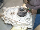 24. Remove input shaft retainer clip from rear case.
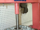 25. After removing the bearing retainer, press input shaft out of case.
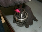 26. Remove bearing retainer clip from input shaft .
 27. Remove bearing from input shaft using a bearing splitter
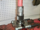 28. Press bearing on to new input shaft
 29. Re-install clip onto input shaft
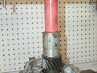 30. Press input shaft into case.
 31. After pressing input shaft back into case, re-install input shaft bearing retainer clip.
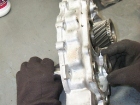 32. After installing input shaft in rear case, install new counter gear shaft onto rear case. Slide the gear shaft into the case from the back side as shown.
 33. Insert the shaft through the thrust washer, then counter gear as shown.
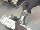 34. Install counter shaft needle bearings and spacer.
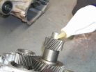 35. Pre-lube the counter gear needle bearings with a squirt of the supplied gear oil. This will allow you to spin the gears freely during final assembly of case halves.
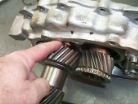 36. IMPORTANT! You have now reached one of the trickiest and most critical steps in this installation. Before the installation of the counter gear into the rear case halve is complete, you must have properly inserted the thrust washer lock ball into the counter shaft. This procedure is opposite, not just the reverse of the stock assembly procedure. If it is not correctly and fully inserted into the shaft, the thrust washer will rotate against the aluminum case and cause major damage to the thrust washer and case surface. The following steps should be followed very carefully.
 37. Insert the thrust washer lock ball using a punch or piece of 1/4 rod. Use a dab of grease on the end of the rod to hold the ball.
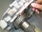 38. The thrust washer is now sitting between the case and counter gear on the shaft. The lock ball must be inserted to keep the thrust washer staked to the shaft against the case. The counter gear will slide out away from the case far enough to allow you to slide the rod with the ball attached between the case and gear. Insert the ball into the slot and be completely sure that the lock ball is inserted completely and that the thrust washer cant rotate against the case.
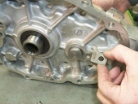 39. After the thrust washer and lock ball are correctly located, push the counter shaft as far as possible through the case and install counter shaft lock plate. Torque to 20.0 ft. Lbs.
 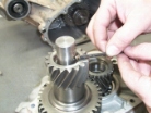 40. After locking tab is installed to shaft, lay case flat and install thrust washer lock ball on opposite end of shaft.
41. Re-install thrust washer over counter gear shaft and onto lock ball.
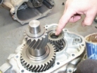 42. Re-install needle bearing into end of input shaft. Grease thoroughly. Apply gasket sealer to both case halves before assembly. No paper gasket is used or available.
 43. Level the rear case halve up on blocks and drop main case into position.
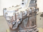 44. Check that the re-assembled case is sealed all around. Check for nicked or torn seals. Torque case bolts to 20.0 ft. Lbs.
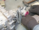 45. Re-install gear shift lever case. Torque to 10.0 ft lbs.
 46. Re-install 4wd switch lead plugs into output end of case. Refer to factory manual for reinstallation procedure of transfer case into vehicle, and fill with gear oil before starting the vehicle.
An easy install for what is probably the best modification you can do to your Sidekick. Unlike the Samurai, we might suggest getting the lift and tires you want first and start enjoying your Sidekick on the easier trails. Once you’ve got a good toehold on that type of terrain and you want to step up to more difficult endevours, the RockCrawler transfercase reduction gear set from CALMINI is for you.

 ZUKIWORLD Online – Everything Suzuki Your Complete Suzuki Automotive Resource for Editorial, Tech, Events, Adventure, Racing, and Forum



Boa noite.
Sou do Brazil e gostaria de instalar no meu vitara um Rock crawler deste na minha t case. vc tem este kit para venda.
Fico no aguardo
Obrigado.