Mike Hagen’s Tips To Modify Your Sidekick.
Editor: Eric Bewley Story/Photo: Mike Hagen
COTTAGE GROVE, MN. To answer the first question of “Why?”, will take a while. Our original reason for doing this modification was to be able to use the left axle shaft in the right side. This would make it far easier to swap axle shafts on the trail and we would only need one spare. Just in case you didnt already know this, to swap out a left shaft you dont even need to remove a wheel. If you leave the front center caps off you can remove the six 12mm bolts at the hub and remove the lockout. Then remove the retainer ring, and the three 14mm bolts on the inner cup. Then find a couple of your heaviest friends to hang on the front of the vehicle so you can pull the shaft out of the knuckle. We wanted this same convenience for the passenger side as well.
We soon realized that we had also gained almost 2 degrees of caster. Caster is an alignment angle that helps a vehicle track straight. If a vehicle gets too much caster then it can turn harder. This is not the case here. If it does turn harder, nobody has noticed. Your increased caster will cause your tracker/kick to drive straighter than it ever has.
The tire will also sit 1 inch forward in the wheel-well allowing for a larger tire or wider wheel. Actually, if you look close the tire on a lifted tracker/kick, it sits towards the back of the wheel-well. This mod just centers it. This also means one more inch of approach angle.
Another benefit is that now that the wheel sits out 1 more inch there is more leverage on the coil and it helps the front flex easier. Sticking out 1 more inch also means that you can turn sharper since the tire wont hit the frame.
With all that being said, there is one side effect. Steering bump-stops have to be adjusted properly. Improper steering adjustment or if you bend a front-end part, (tie rod, drag link, Idler arm) and the steering is allowed to turn too far, the caliper may turn so far it runs into the coil. This forces the piston back in the caliper and you wont have a brake pedal until the second pump. Normally the tire would hit the frame first but the tire now clears the frame. If everything is adjusted properly then this wont happen. It doesnt happen often, or to everyone, but if it does it can be pretty scary.
Begin: PERFORMANCE PREP:
This requires welding, drilling, three spare three bolt inner axle shafts, spare left side CV shaft, and a chop saw or cutoff wheel.
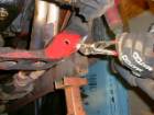
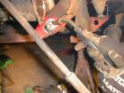
Lift and support the vehicle by the frame. Remove the lower control arms and coils. Drain front diff fluid. Remove the right axle shaft. Remove three bolt-inner axle from housing. Flatten frame as shown.
Draw a straight line between the existing hole and the edge of the front of the frame. Find the halfway point and mark it with a center punch. Drill a ½ inch hole here. Do not drill the backsides yet.
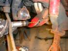
Install the front control arm bolts loosely, connect the ball joint, and line up the rear holes and slide the drill bit through the hole.
Drill long enough to leave a good starting point. Remove the control arm again. Drill the rear holes.
Install some thick quality washers on both sides of your new holes. I recommend that you weld the washers to the frame for additional strength.
If you do not, the bolts could tear through the frame under hard off road use. Now install the control arms.
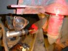
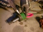
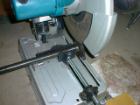
Next on to the shafts. Remove the Inner cup from the right side CV shaft and cut it as straight as possible on the factory stamped line as shown.
Cut the three-sided shaft at the base as shown. Heres how they should look at this point.
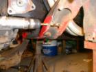
Set the cup on top of the base and center as shown. Tack weld it together. Pop it into the housing and spin it to see how round it is. If its good then finish welding it all the way around.
Now if your not exited about welding an axle remember this, the weld is 4 inches around. Its more like a weld on a drive shaft, except its larger. Now for the drivers-side axle. Cut two more bases, stack them on and weld them. It is very important that these are welded. It looks like you could just bolt them in as spacers and call it good. What will happen is the torque will cause it to shift and twist off the bolts. Weld it. You will need three 3/8 grade 8 bolts three inches long. Normally, I would show you a picture of this side but unfortunately this is when our heater went out and the digital camera wouldnt work anymore because it was just too cold!
Next, the alignment. The front will lower slightly, up to ½ inch. To correct this, we add a ½ spacer to some if they need to be leveled. Camber will also dip in slightly. Remember to level your vehicle before adjusting camber. One method for adjust camber is by hawging the upper strut holes for more adjustment. IMPORTANT: After the alignment is done be sure to adjust your steering stops on the pitman arm to prevent the caliper from pushing against the coil. Remember to give yourself some room for error.

 ZUKIWORLD Online – Everything Suzuki Your Complete Suzuki Automotive Resource for Editorial, Tech, Events, Adventure, Racing, and Forum



sx4 rear diff fllange right and left fits
Are you welding (2) additional flange cut offs onto the drivers side only? Or do I weld (1) spacer on each side?
If I had calmini 3″ suspensión lift, I need to do the modification