 ZUKIWORLD Online – Everything Suzuki Your Complete Suzuki Automotive Resource for Editorial, Tech, Events, Adventure, Racing, and Forum

Strengthening The Sidekick Using Calmini’s Anvil And Factory Suzuki Parts.
Editor: Eric Bewley Story/Photo: Bryan Zeigler
BRENTWOOD, TN -Most people that have built their Sidekick for off-road use have encountered problems with the strength (or lack of) with the front driveline. Once you have added oversize tires, lockers and lower gears, the half shafts are usually the first to break.

Then there comes the dreaded metallic snap as the aluminum housing snaps off at the mounting bracket. In my quest to find a good dependable set up for the front end, I decided to start with the axle and third member housings. After posting many questions and receiving many great responses form the members of the Zukiworld.com BBS board, I decided to go with the Calmini Anvil and an XL-7 third member. This would allow for easier trail fixes of the half shafts, give me an stronger set up, and if needed make it easier to determine how to accomplish a stronger CV set up.
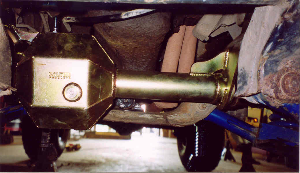
Calmini’s Anvil replaces the passenger side half shaft with an inner stub axle and another drivers side half shaft. This allows the driver to carry one replacement axle and makes for easier trail fixes. The XL-7 housing is almost identical to the Grand Vitara housing that is recommended for this application. The only difference is the XL-7 housing has a different mounting bracket and a much larger tab that holds the mounting bracket to the housing.
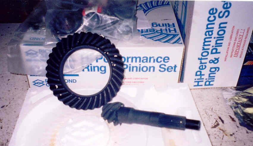
Before I get to the install of this set up here is a list of the items that were needed and/or used for the project; – Calmini Anvil housing, Grand Vitara XL-7 third member housing, modified Samurai Carrier, 26 spline side gears, Detroit EZ Locker, 5.83:1 Richmond Gear set and install kit from Calmini, and an extra drivers side half shaft.


The Removal:
1-To begin your install raise you vehicle and support it with jack stands, remove your front wheels and drain the oil from your front axle. 2-Remove the lockout hubs and the C-Clip on the half shafts.  3- Disconnect the bolts that mount the drivers side half shaft to the housing. 4- Support each control arm with a floor jack and add just enough pressure to barely compress the spring.
  5- Remove the struts by disconnecting the three upper mounting nuts, the three lower mounting nuts and the break line retention clip. 6- Remove the 4 castle nuts that hold the tie rod in place. 7- Using a ball joins seperator, remove the tie rod
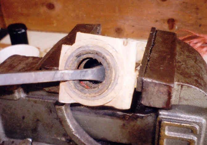
 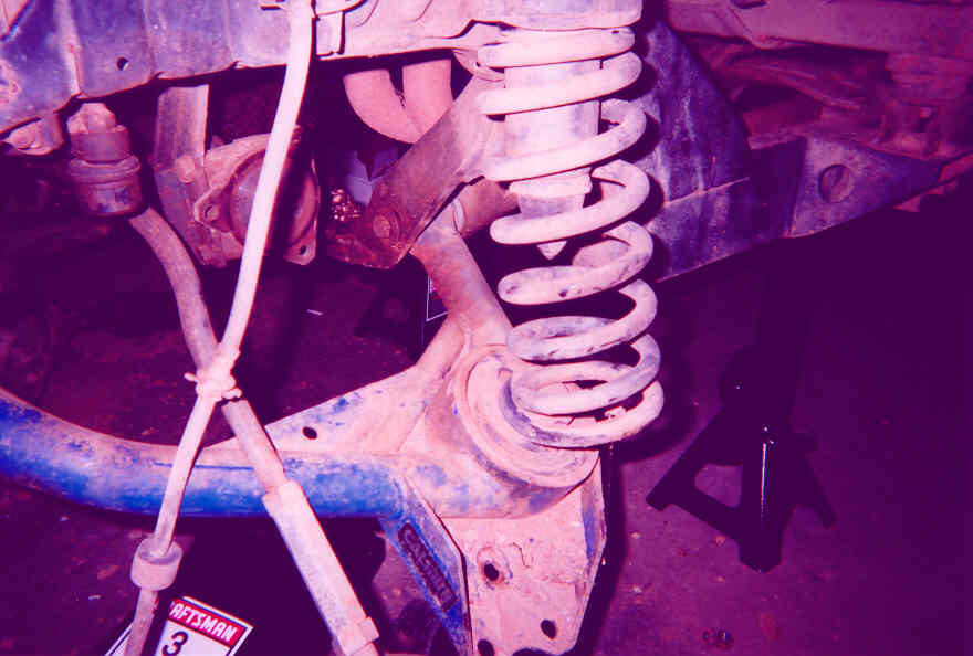 8- SLOWLY lower both control arms until the springs and the half shafts can be removed. *NOTE* Be careful not to bind the passenger side half shaft, you will need to use a pry bar between the housing and the inner cup to start the half shaft out of the housing. Once the half shafts and springs have been removed let the control arms hang
 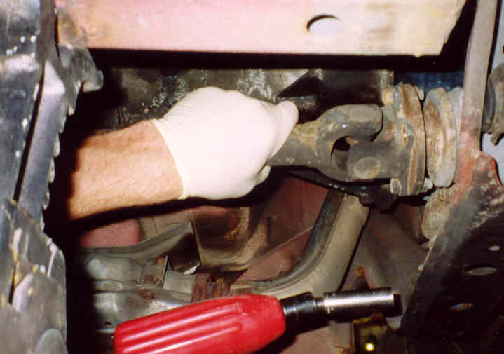 9- Remove the four drive shaft bolts and tie the loose end of the shaft to the frame or any location that is out of the way. 10- Remove the two bolts that hold the third member mounting bracket to the cross member.
  11- Support the axle with a floor jack and disconnect the two front mounting brackets. 12- Lower the floor jack and remove you axle.
Dissesembly of the Axle
 1- Use a rubber mallet or slide hammer and remove the inner axle
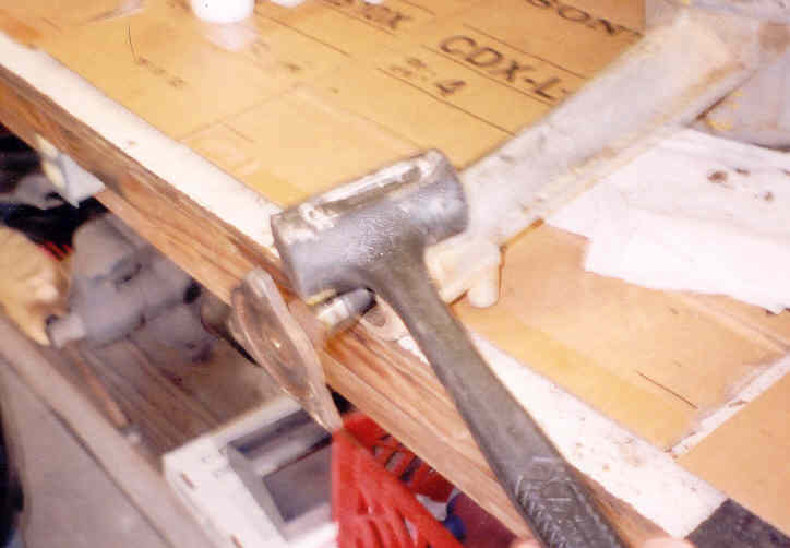
 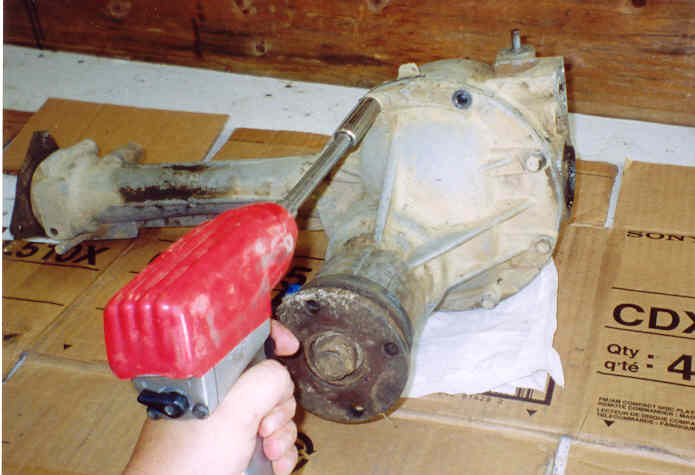 2- Remove the nuts holding the third member to the axle housing 3- Remove the third member from the housing (sounds simple enough). This step may take allot of time if you plan to sell/use the housings again. Use a pry bar and a rubber mallet to beat and pry until the housings seperate.
Assembly of new Axle:
Due to my lack of knowledge in ring and pinion set up, I had a reputable mechanic do the assembly of the new Axle. I supplied him with a modified Samurai carrier from Hawk Strictly Suzuki, 26 spline side gears, Detroit EZ Locker, 5.83:1 Ring and Pinion from Calmini and an XL-7 cast third member housing. At the low cost of a few cold ones and about 30 minutes of time, I had everything ready to install into the Calmini Anvil housing.
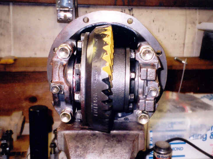
Once you have your ring and pinion set up you are ready to assemble your new axle. The Anvil comes with the housing, magnetic drain plug, vent tube attachment, new bearings w/ c-clips for the new stubshaft, and bushings for the built in mounting brackets.
1- Install the bushings and sleeves into the Anvils built in mounting brackets using the suplied bushing lube.
2- Install the inner axle bearings and retaining C-Clip
3- Install the vent tube mount and the magnetic drain plug.
4- Apply gasket maker and install the XL-7 third member.
5- Install the inner axle shafts.
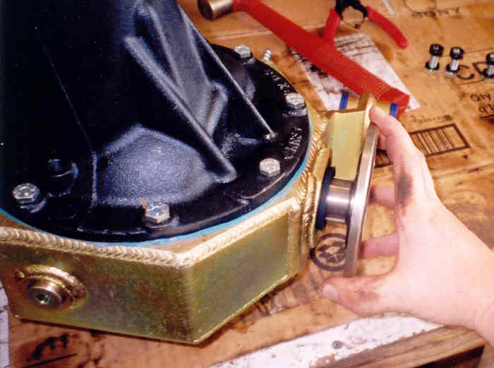
6- Install the XL-7 rear mounting bracket and your Anvil is ready to go in the truck.

Installing the Complete Axle (the balancing act):
This is where the removal of the tie rods comes in. It allows enough room to raise the complete axle w/ built in upper mounts into place.
Before you begin to install the axle in the truck, use any left over bushing lube on the outter edges of the bushings. This will allow the slide into place MUCH easier and make alligning the bolts easier.
1- Place the axle on a floor jack with the third member facing up and roll axle under the front of the vehicle.
2- Balance the axle at a 45 deg angle and begin to raise into place.
3- As you raise the axle into place, feed the end of the third member into place while keeping the mounting brackets heading towards their brackets.
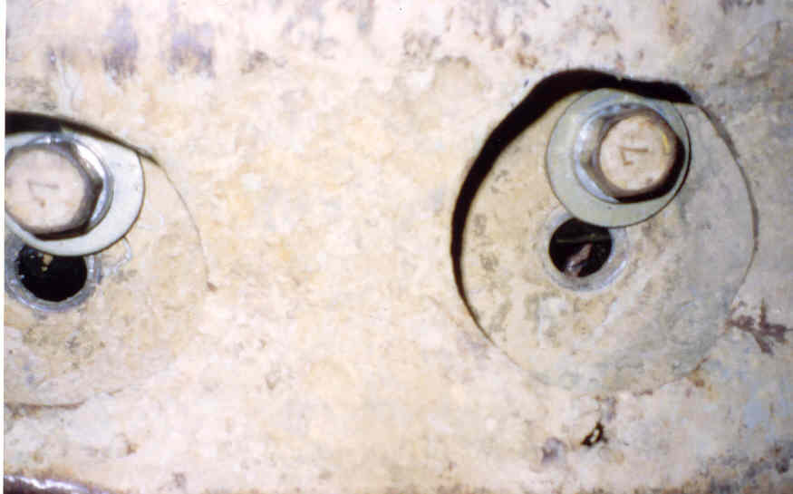
4- Once the rear mount is between the Oil Pan and the cross member, allign the upper mounts and install the mounting bolts.
5- Using a pry-bar, TRY to align the rear mounting bracket. The bracket will be binding on the mounting plate. Mark both sides of the mounting bracket for grinding, remove it and grind off the lip that is causing the bind.
6- Reinstall the rear mounting bracket.
7- This try you should be able to pry the mount until it is flush with the crossmember, and install the mounting bolts.
* Due to many years of off-road abuse, my cross-member was very bent up and the mounting bracket did not align with the mounting holes. I had the choice of using a port-a-power and re-shaping my cross member or drilling new holes for the mount. After taking measurments to make sure nothing would bind, I decided to drill new holes in the cross member.
Re-assemble front end:
1- Reconnect the driveshaft.
2- Support control arms with a floor jack.
3- Insert half shaft through hub and install retaining clip. Leave the half shafts lying in the control arm.
4- Install coil springs and raise control arm until the coils are compressed just enough to reinstall your struts.
5- Reinstall the struts.
6- Reinstall the tie rod, be sure to replace any worn cod-pins for the castle nuts.
7- Reinstall your hubs and wheels.
8- Check all bolts and fill your diff oil and your ready to try it out.


If my problem was a Death Star, this article is a photon todpreo.