How-To: Suzuki Samurai mini-spool installation
Canon Beach, OR – Story/Photos: Matt Verley
I’ve seen the “how hard is it to install a locker in my samurai?” about a dozen times in one way or another; and I didn’t see a comprehensive set of instructions with pics. So, since I put the spool in the back of a Samurai this evening, AND I see WAY too many people skipping the locker/spool install because they’re afraid of digging into the rear axle of their rig, I thought I would take some time to do a quick writeup.
This procedure is nearly identical for the rear of a tracker/sidekick, and the Toyota pickup axle. And it is similar for most axles with a removable 3rd member with some minor differences. A lock-rite or EZ locker install is essentially the same as well…no significant differences. Installing an ARB or Detroit (or anything that replaces the carrier) requires more attention to be paid to the gear setup. I’ve done about a dozen Samurai axles, and this took me about 3 hours. I would expect that just about any backyard mechanic could do it in less than 5.
I did this without using my dial indicator or in-lb torque wrench to show that it can be done without these tools. In fact, this requires very few tools. The only (somewhat) special tools I used were a slide hammer and a ft-lb torque wrench. The slide hammer isn’t necessary…but it sure saves a lot of time and swearing. Yes, the “proper” way to do this is to completely set up the gears after disassembly, but if careful attention is paid to the gear setup when you disassemble the 3rd member, it is quite easy to put back together and even though I have the tools to set up gears, I don’t bother if I’m just replacing the spiders with a locker/mini-spool.
Tools used:
|
Here is a list of the materials used:
|
OK! Here we go:
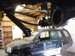
- Jack the rig up and put it on jackstands.
- Release the emergency brake.
- Using the 3/8” ratchet and extension, remove the drain plug and drain all of the gear oil out of the differential
- Remove both rear wheels (I find that the center caps are handy for storing all of the bolts and hardware for each side)
- Remove the 4 bolts holding the brake drum to the axleshaft
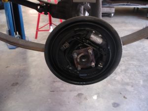
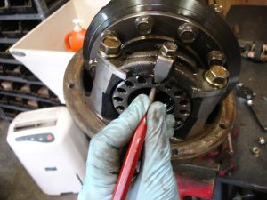
6. Remove the brake drum. Ususally, a few blows with the deadblow hammer on the 4 studs will jar the drum loose. If this doesn’t work, LIGHTLY tap it with the ball peen hammer. If this still doesn’t work, reinstall the nuts on the 4 studs to protect the threads and hit them harder with the hammer. This might result is pressing the studs out of the axle; don’t worry, when you reinstall them and tighten the nuts they will be pulled back into place. With the brake drum removed, clean the brake hardware with a can of brake cleaner. Don’t use compressed air, as this can cause lots of potentially harmful brake dust to become airborne.
7. Using needlenose pliers, remove the clip and pin holding the e-brake cable to the arm on the back of the backing plate.
8. Fill your master cylinder to the top with brake fluid. Using the flare nut wrench, remove the brake lines from the backing plate, and cover them with the vacuum caps. The use of vacuum caps isn’t necessary, but it prevents air from entering the brake system at the master cylinder and makes the brakes easier to bleed later. You can also just use a 10mm wrench to remove the brake lines, but you risk damaging the flare nut and a trip to the parts store to buy a new brake line.
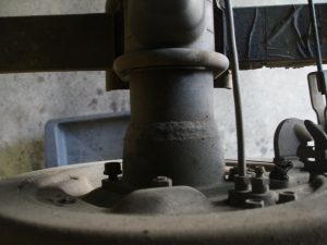
9. Now, remove the 4 bolts holding the backing plate to the axle housing.
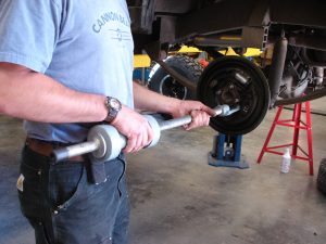
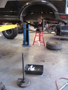
10. Place something to catch the oil underneath the end of the axle. Then, using the slide hammer (or prybars, sledgehammers, and lots of four letter words), pull the axleshaft out of the axle housing. Be careful not to damage the seal inside of the axle housing. It is also possible to use the tire and wheel as a makeshift slide hammer; just loosely install a few of the lugnuts and use the weight of the tire/wheel to pull the axle out. Be warned, this might cause a bit of damage to the wheel studs if you aren’t careful.
11. Now is a good time to inspect your wheel bearings. If there is ANY play in the bearing, it should be replaced.
12. Perform steps 5-11 on the opposite side of the vehicle.
13. Remove the 4 bolts holding the driveshaft flange to the pinion flange
14. Remove the bolts holding the 3rd member in the axle housing. I’ve found the best way to break it loose is to use a jack on the pinion flange and apply gentle upward pressure. DON’T force a screwdriver in between the sealing surfaces; you risk scarring the surfaces and a gear oil leak.
15. Using a punch, mark the location of both bearing adjuster nuts and bearing caps. It is important that they go back in their exact locations. Note how many threads are showing inside each of the bearing caps. This will allow you to screw the bearing nuts back to their original positions when you re-assemble the 3rd member. Also, turn the pinion by hand and get a feel for how difficult it is to turn, and how much backlash there is (keep the pinion from moving and rock the differential back and forth). There should be just a very slight drag, and a noticeable (but very small) amount of backlash.
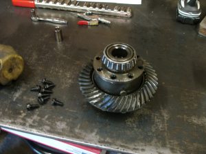
16. Next, remove the 2 bearing nut retainers, and the 4 bearing cap bolts and remove the bearing caps. Make sure you keep track of which side the bearing races came off of. Remove the carrier and set it on a clean work surface.
17. Remove the 8 bolts holding the carrier cover on and remove the cover
18. Remove the 10 bolts holding the ring gear to the carrier and remove the ring gear
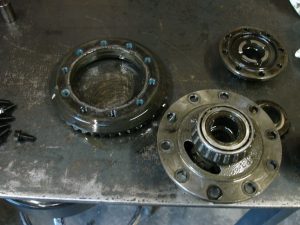
19. Push the crosspins out of the carrier. They should slide out easily.
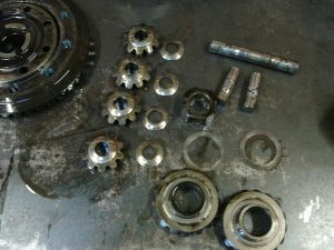
20. Remove everything from inside of the carrier. You should get 2 side gears and side gear washers, 4 spider gears and spider gear washers, the center cross, and 3 crosspins. You will be re-using the crosspins. Also, save the side gears as they are useful for front axle upgrades. The spider gears and washers can be discarded.
21. Install the locker/mini-spool in the carrier. Do not use any washers.
22. Replace the carrier cover and, using loctite on the threads, torque the 8 bolts to 45 ft-lbs
23. Thoroughly clean the ring gear mounting surface and the surface on the carrier. Any foreign objects here will prevent the ring gear from seating properly and will cause noisy gears and premature wear. Reinstall the ring gear using loctite and torque the bolts in a crisscross pattern to 60 ft-lbs.
24. Reinstall the carrier into the 3rd member housing and snug up the bearing cap bolts but do not torque yet. Install the bearing adjuster nuts and return them to their original positions. Rotate the pinion by hand and check the backlash. If you positioned the bearing adjuster nuts properly, it will feel exactly the same as it did in step 15. The nuts can be adjusted using a punch and a hammer, or you can make a tool with a piece of flat bar and some ¼” bolts and nuts.
25. Torque the bearing caps to 65 ft-lbs and reinstall the bearing nut retainers.
26. Put a thin layer of permatex on the 3rd member mounting flange, and reinstall the 3rd member in the axle housing. Snug the bolts enough to force some of the sealant out around the flange, but wait 1 hour to fully tighten all of the bolts.
27. Clean both axleshaft seals and the axleshaft sealing surfaces, then slide the axleshafts back into the housing. Be careful not to damage the axle seals. Use a deadblow hammer or rubber mallet to seat the bearings in the axle housing.
28. Connect the brake lines to the slave cylinders, and reconnect the e-brake cables.
29. Install the 4 backing plate bolts. No sealant is necessary between the backing plate and the axle housing. If you have a leak showing up here, it means that your axle seal (and probably your wheel bearing) is bad.
30. Reinstall the brake drums and tighten the 4 axle flange nuts.
31. Reinstall your driveshaft and tighten the 3rd member bolts.
32. Refill the master cylinder with brake fluid, and crack the bleeder valve (or valves) on your wheel cylinders. Allow the brake fluid to flow from the valves for about 5 minutes. During this time, keep filling the master cylinder to keep the level above the minimum mark. This method of brake bleeding is slow, but it only requires one person and usually works quite well. If the brake pedal feels spongy after you are done, open the valve again and allow fluid to flow for a few more minutes. Eventually all of the air will work its way out of the system.
33. Fill the rear differential with gear oil. It should take about 1.5 quarts.
34. Find a pile of rocks or some deep ruts. Drive your rig through the obstacle. Note how awesome it is with the locker installed. Tell your friends that you can help them install a locker in their rig for beer and pizza. Get lots of free beer and pizza.
![]()
 ZUKIWORLD Online – Everything Suzuki Your Complete Suzuki Automotive Resource for Editorial, Tech, Events, Adventure, Racing, and Forum





Great write up. Helped me a lot. I do have a concern with the 45 ft-lbs torque for the 8 carrier cover bolts. I managed to break one, and severely stretched most of the others. I believe 45 ft-lbs is too high for the M8x1.25 flange bolts. I saw another post in a forum refering to 20 ft-lbs. I have not check the Factory Service Manual, yet.
Luckily I was able to back the broken off bolt out of the carrier with a punch in counter clockwise taps. The lock tite had not set yet.
Just trying to save others some trouble.
Thanks.
Eddie.